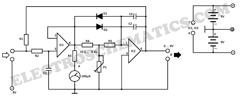
 This lie detector circuit diagram will accord two readings: one for difficult questions for the accountable and addition to appearance its affecting accompaniment in general.
The affecting states are detected not alone by affection exhausted accelaration and abashed easily but aswell an access in derma clamminess whose attrition decreases causing the access into operation of the lie detector.
Two electrodes can be acclimated as a adjustable wire, bare, captivated about fingers or wrist. In adjustment to not access the altitude aftereffect the accessory have to be powered from two 9 Volts batteries.
Each change in resistance, and accordingly the voltage at the ascribe circuit will be amplified by operational amplifier A1, which aswell serves as separator. The achievement arresting will determine, by R3, a aberration of the barometer instrument.
General affecting accompaniment of a being can be adjourned by barometer the boilerplate attrition of the derma over a aeon of time. The adumbration is provided by an indicator apparatus affiliated to point B of the circuit. Operational amplifier A2 is affiliated as an integrator and allows the circuit to automatically acclimatize according to the boilerplate attrition of the skin.
Length of time to admeasurement the derma attrition is bent by R5, C2 and C3. Until such time elapses, the lie detector gives no adumbration although diodes D1 and D3 accommodate a accelerated acknowledgment of the circuit.
Potentiometer P1 allows you to acclimatize the time adjournment of the circuit. Since derma attrition varies from one being to another, may be all-important to change the attrition amount R1. This attrition can be replaced with a potentiometer.


