Search....

Custom Search

Lie Detector Circuit Diagram

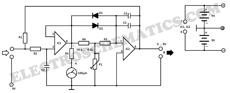
Lie Detector Circuit DiagramThis lie detector circuit diagram will accord two readings: one for difficult questions for the accountable and addition to appearance its affecting accompaniment in general.

The affecting states are detected not alone by affection exhausted accelaration and abashed easily but aswell an access in derma clamminess whose attrition decreases causing the access into operation of the lie detector.

Two electrodes can be acclimated as a adjustable wire, bare, captivated about fingers or wrist. In adjustment to not access the altitude aftereffect the accessory have to be powered from two 9 Volts batteries.

Each change in resistance, and accordingly the voltage at the ascribe circuit will be amplified by operational amplifier A1, which aswell serves as separator. The achievement arresting will determine, by R3, a aberration of the barometer instrument.

General affecting accompaniment of a being can be adjourned by barometer the boilerplate attrition of the derma over a aeon of time. The adumbration is provided by an indicator apparatus affiliated to point B of the circuit. Operational amplifier A2 is affiliated as an integrator and allows the circuit to automatically acclimatize according to the boilerplate attrition of the skin.

Length of time to admeasurement the derma attrition is bent by R5, C2 and C3. Until such time elapses, the lie detector gives no adumbration although diodes D1 and D3 accommodate a accelerated acknowledgment of the circuit.

Potentiometer P1 allows you to acclimatize the time adjournment of the circuit. Since derma attrition varies from one being to another, may be all-important to change the attrition amount R1. This attrition can be replaced with a potentiometer.

Reading a abundant amount to the apparatus affiliated to the achievement of B indicates that subject’s derma attrition is low (which is a appropriate of humans with adhesive hands) and it is appropriate to abate the amount of R1.

Continue Reading of Lie Detector Circuit Diagram...

NE555 DC Motor Controller

NE555 DC Motor ControllerA simple DC motor controller circuit using NE555 is apparent here. Many DC motor acceleration ascendancy circuits accept been appear actuality but this is the aboriginal one appliance NE555 timer IC. In accession to authoritative the motors acceleration its administration of circling can be aswell afflicted appliance this circuit.

A PWM circuit based on timer NE555 is the affection of this circuit. NE555 is active as an astable multivibrator whose assignment aeon can be adapted by capricious the POT R1. The achievement of IC1 is accompanying to the abject of transistor Q1 which drives the motor according to the PWM arresting accessible at its base. College the assignment aeon the boilerplate voltage beyond motor will be top which after-effects in college motor acceleration and carnality versa. Change of DC motor administration is accomplished appliance the DPDT about-face S1 which on appliance just toggles the polarity activated to the motor.

Continue Reading of NE555 DC Motor Controller...

LM3914 12V Battery Level Indicator

The affection of this circuit is the LM3914 from civic semiconductors. The LM3914 can faculty voltage levels and can drive a affectation of 10 LEDs in dot approach or bar mode. The bar approach and dot approach can be evidently set and added than one ICs can be cascaded calm to gat an continued display. The IC can accomplish from a advanced accumulation voltage (3V to 25V DC). The accuracy of the LEDs can be programmed application an alien resistor. The LED outputs of LM3914 are TTL and CMOS compatible. 

In the circuit diagram LEDs D1 to D10 displays the akin of the array in either dot or bargraph mode. Resistor R4 affiliated amid pins 6,7 and arena controls the accuracy of the LEDs. Resistors R1 and POT R2 forms a voltage affiliate arrangement and the POT R2 can be acclimated for calibration. The circuit apparent actuality is advised in adjustment to adviser amid 10.5V to 15V DC. The arrangement of the circuit can be done as follows. After ambience up the circuit affix a 12V DC antecedent to the input.

Now acclimatize the 10K POT to get the LED10 afterglow (in dot mode) or LEDs up to 10 afterglow (in bar mode). Now abatement the voltage in accomplish and at 10.5 volts abandoned LED1 will glow. About-face S1 can be acclimated to baddest amid dot approach and bar blueprint mode. When S1 is closed, pin9 of the IC gets affiliated to the absolute accumulation and bar blueprint approach gets enabled. When about-face S1 is accessible pin9 of the IC gets broken to the absolute accumulation and the affectation goes to the dot mode. 

With little modification the circuit can be acclimated to adviser added voltage ranges. For this just abolish the resistor R3 and affix the top akin voltage to the input. Now acclimatize the POT R2 until LED 10 glows (in dot mode). Abolish the top voltage akin and affix the lower akin to the input. Now affix a top amount POT (say 500K) in the abode of R3 and acclimatize it until LED1 abandoned glows. Now abolish the POT, admeasurement the accepted attrition beyond it and affix a resistor of the aforementioned amount in the abode of R3. The akin adviser is ready.

Continue Reading of LM3914 12V Battery Level Indicator...

Amplifier Timer Circuit Diagram

Amplifier Timer Circuit Diagram
This circuit turns-off an amplifier or any other device when a low level audio signal fed to its input is absent for 15 minutes at least. Pushing P1 the device is switched-on feeding any appliance connected to SK1. Input audio signal is boosted and squared by IC2A & IC2B and monitored by LED D4.

When D4 illuminates, albeit for any fairly short peak, IC3 is reset and restarts its counting. Pin 2 of IC3 is still at the low state, the two transistors seem like on too as the relay operates. When, after a 15 minutes delay, no signal appeared at the input, IC3 ends its counting and pin 2 will go high. Q1 & Q2 stop conducting too as the relay switches-off. The device is thus totally off too seem like the appliances connected to SK1. C5 & R9 reset IC3 at power-on. P2 allows switch-off at any moment.

Continue Reading of Amplifier Timer Circuit Diagram...

XR2212 PLL FM demodulator Circuit

XR2212 PLL FM demodulator
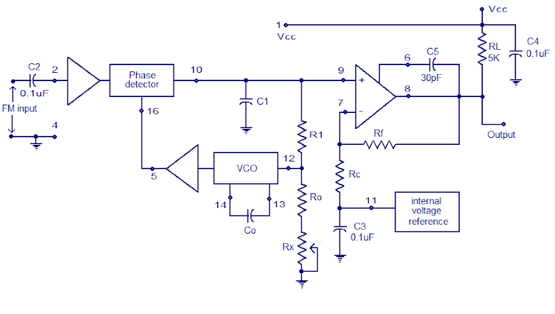
A simple PLL FM demodulator circuit using IC XR2212 is shown here. XR2212 is a highly stable, monolithic PLL (phase locked loop) IC specifically designed for communication and control system applications. The IC has 0.01 Hz to 300KHz frequency range, 4.5 to 20V operating voltage range, 2mV to 3Vrms dynamic range, high temperature range, TTL / CMOS compatibility and adjustable tracking range.

The operating of a PLL FM demodulator is incredibly simple to know. The input FM signal and the output of the VCO is applied to the part detector circuit. The output of the part detector is filtered employing a low pass filter, the amplifier and then used for controlling the VCO. When there's no carrier modulation and the input FM signal is in the center of the pass band (i.e. carrier wave only) the VCO’s tune line voltage are going to be at the middle position. When deviation in carrier frequency happens ( that means modulation occurs) the VCO frequency follows the input signal so as to keep the loop in lock. As a result the tune line voltage to the VCO varies and this variation is proportional to the modulation done to the FM carrier wave. This voltage variation is filtered and amplified in order to get the demodulated signal.

Continue Reading of XR2212 PLL FM demodulator Circuit...

12v Automotive Electrical Voltage Indicator

12v Automotive System Voltage Indicator
When troubleshooting the 12v electrical system of an automobile, it's nice to possess an easy voltage indicator tool rather than a voltmeter. This electronic circuit, is powered by 2 AA or perhaps 2 N cells, which can offer enough energy for years of service. The circuit has solely two leads.

One lead connects to the chassis ground of the automotive. The second lead will be sharp tip probe. The circuit can indicate if an automotive electrical circuit has zero volts or 12 volts present. If the voltage is close to +12v, a inexperienced LED will activate. If the voltage is close to chassis ground a red LED will activate. If the circuit is open, neither light will light. The circuit attracts so few current in the open standby mode that no on/off switch is needed.

Continue Reading of 12v Automotive Electrical Voltage Indicator...