
Ic 555 is an integrated circuit (chip) implementing a range of timer and multivibrator applications. The IC was designed by Hans R. Camenzind in 1970 and delivered to market in 1971 by Signetics (later acquired by Philips). the original name was the SE555 (metal can)/NE555 (plastic DIP) and the part was described as "The IC Time Machine". it's been claimed that the 555 gets its name from the three 5-kohm resistors utilized in typical early implementations, however Hanz Camenzind has stated that the quantity was arbitrary The part continues to be in wide use, because of its easy use, low price and sensible stability. As of 2003 it is estimated that one billion units are manufactured every year.
Depending on the manufacturer, the quality 555 package includes over twenty transistors, 2 diodes and fifteen resistors on a silicon chip put in in an 8-pin mini dual-in-line package (DIP-8).
The 556 could be a 14-pin DIP that combines two 555s on one chip. The 558 could be a 16-pin DIP that combines four slightly changed 555s on one chip (DIS & THR are connected internally, TR is falling edge sensitive instead of level sensitive).
Also accessible are ultra-low power versions of the 555 like the 7555 and TLC555. The 7555 requires slightly different wiring using fewer external elements and fewer power.
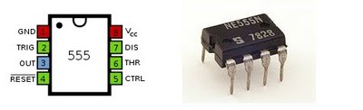
The connection of ic 555 as follows:
- GND(1)Ground, low level (0V)
- TRIG(2)A short pulse high-to-low on the trigger starts the timer
- OUT(3)During a timing interval, the output stays at +VCC
- RESET(4)A timing interval can be interrupted by applying a reset pulse to low (0V)
- CTRL (5)Control voltage allows access to the internal voltage divider (2/3 VCC)
- THR (6)The threshold at which the interval ends (it ends if U.thr → 2/3 VCC)
- DIS (7)Connected to a capacitor whose discharge time will influence the timing interval
- V+, VCC(8) The positive supply voltage which must be between 3 and 15 V


